
Hướng dẫn cấu hình định tuyến trên Firewall Fortigate.
Cấu hình định tuyến trên Firewall Fortigate (Phần I)
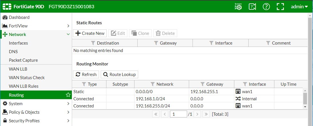
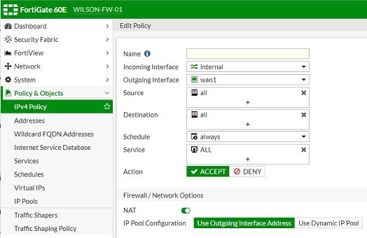
1. Cấu hình và kiểm tra Default Route trên Firewall Fortigate Version 5.4.
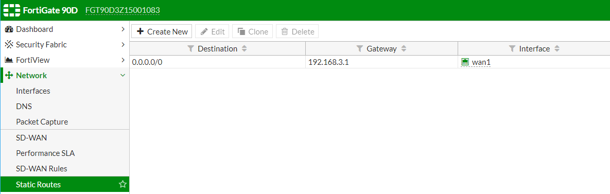
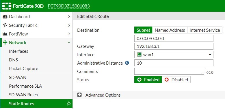
2. Cấu hình và kiểm tra Default Route trên Firewall Fortigate Version 6.0.
3. Cấu hình định tuyến tĩnh Static Route trên Firewall FortiGate.
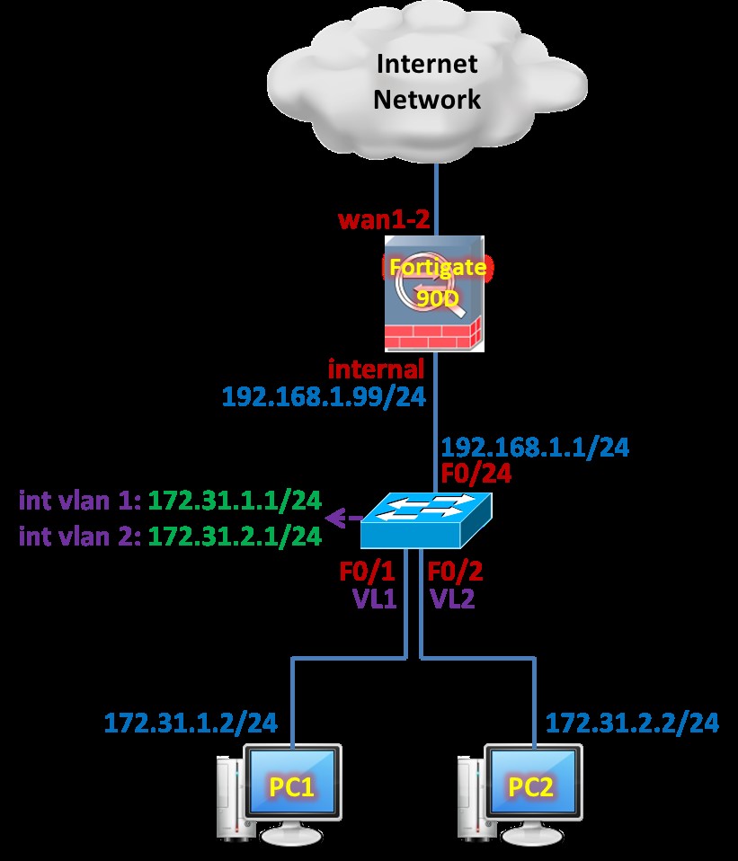
Bước 1. Cấu hình cơ bản trên Cisco Switch.
|
hostname Sw1
default interface f1/0/1 interface f1/0/1 switchport trunk encapsulation dot1q switchport mode trunk spanning-tree portfast trunk exit
vlan 2 exit default interface f1/0/2 interface f1/0/2 switchport trunk encapsulation dot1q switchport mode trunk switchport trunk native vlan 2 spanning-tree portfast trunk exit
interface vlan 1 ip address 172.31.1.1 255.255.255.0 no shutdown exit interface vlan 2 ip address 172.31.2.1 255.255.255.0 no shutdown exit ip dhcp excluded-address 172.31.1.1 ip dhcp pool LAN1 network 172.31.1.0 255.255.255.0 default-router 172.31.1.1 dns-server 8.8.4.4 exit ip dhcp excluded-address 172.31.2.1 ip dhcp pool LAN2 network 172.31.2.0 255.255.255.0 default-router 172.31.2.1 dns-server 8.8.4.4 exit
default interface f1/0/24 interface f1/0/24 no switchport ip address 192.168.1.1 255.255.255.0 exit ip routing ip route 0.0.0.0 0.0.0.0 192.168.1.99
line vty 0 4 privilege level 15 no login transport input telnet exit no ip domain-lookup |
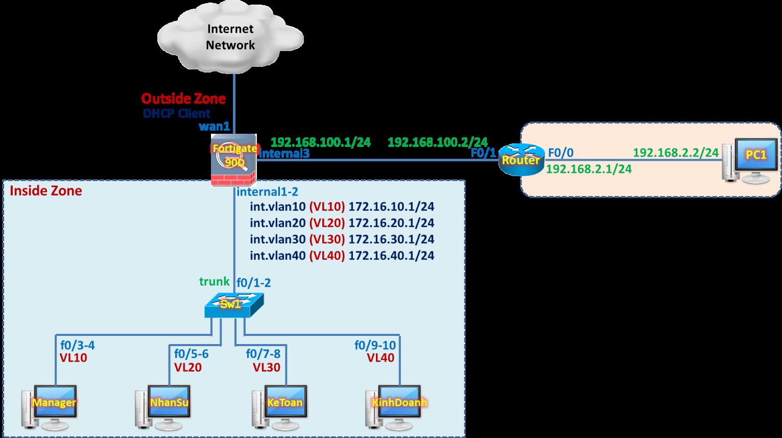
Các bước cấu hình định tuyến tĩnh trên Firewall Fortigate đảm bảo VLAN10 có thể giao tiếp được với PC1 thuộc lớp mạng 192.168.2.0/24.
Bước 1. Cấu hình định tuyến tĩnh trên Cisco Router.
Bước 2. Cấu hình cơ bản trên Sw1.
Bước 3. Đặt IP trên các cổng giao tiếp của Firewall Fortigate.
Bước 4. Cấu hình Static Route trên Firewall Fortigate.
Bước 5. Định nghĩa IPv4 Policy cho phép VLAN 10 có thể giao tiếp được với mạng LAN 192.168.2.0/24.
Bước 6. Định nghĩa Address Object tương ứng với VLAN 10 và mạng LAN 192.168.2.0/24.
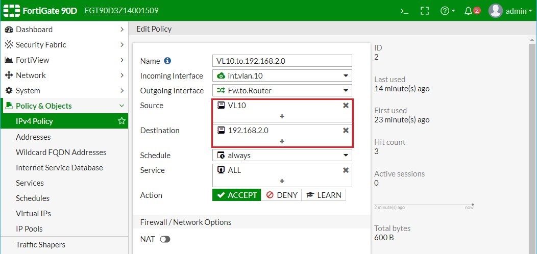
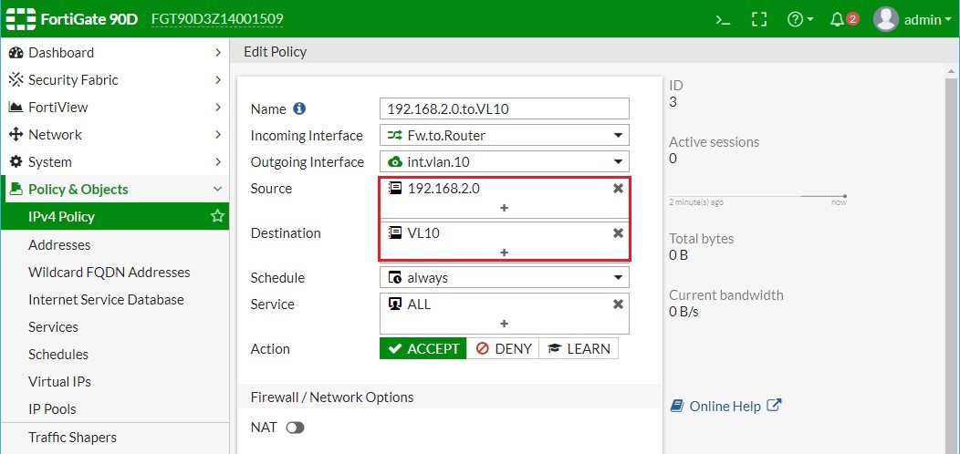
Bước 7. Hiệu chỉnh IPv4 Policy cho phép VLAN 10 có thể giao tiếp được với mạng LAN 192.168.2.0/24 tương ứng với Source và Destination cụ thể.
Bước 1. Cấu hình định tuyến tĩnh trên Cisco Router.
|
hostname Router default interface f0/1 interface f0/1 ip address 192.168.100.2 255.255.255.0 no shutdown exit default interface f0/0 interface f0/0 ip address 192.168.2.1 255.255.255.0 no shutdown no keepalive exit ip route 172.16.0.0 255.255.0.0 192.168.100.1 line vty 0 4 privilege level 15 no login exit line console 0 logging synchronous exec-timeout 0 0 exit no ip domain-lookup no cdp run no service timestamps debug no service timestamps log |
Bước 2. Cấu hình cơ bản trên Sw1.
Cấu hình trên Sw1.
|
hostname Sw1 default interface range f0/1 , f0/2 interface range f0/1 , f0/2 switchport trunk encapsulation dot1q switchport mode trunk switchport nonegotiate exit
vlan 10 exit default interface range f0/3 , f0/4 interface range f0/3 , f0/4 s witchport mode access switchport access vlan 10 spanning-tree portfast exit interface vlan 10 ip address 172.16.10.100 255.255.255.0 no shutdown exit
vlan 20 exit default interface range f0/5 , f0/6 interface range f0/5 , f0/6 switchport mode access switchport access vlan 20 spanning-tree portfast exit
vlan 30 exit default interface range f0/7 , f0/8 interface range f0/7 , f0/8 switchport mode access switchport access vlan 30 spanning-tree portfast exit vlan 40 exit default interface range f0/9 , f0/10 interface range f0/9 , f0/10 switchport mode access switchport access vlan 40 spanning-tree portfast exit default interface range f0/11 , f0/12 interface range f0/11 , f0/12 switchport mode access switchport access vlan 1 spanning-tree portfast exit interface vlan 1 ip address 192.168.1.100 255.255.255.0 no shutdown exit line vty 0 4 privilege level 15 no login exit spanning-tree mode rapid-pvst |
Bước 3. Đặt IP trên các cổng giao tiếp của Firewall Fortigate.


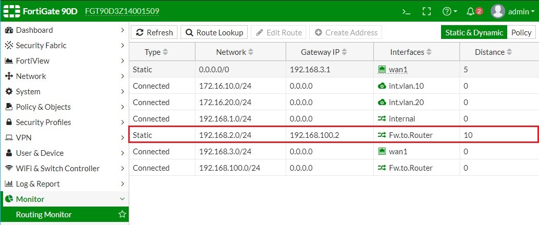
Bước 4. Cấu hình Static Route trên Firewall Fortigate.


Bước 5. Định nghĩa IPv4 Policy cho phép VLAN 10 có thể giao tiếp được với mạng LAN 192.168.2.0/24.
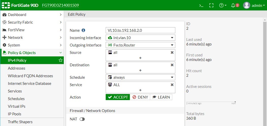
Lúc này thì VLAN 10 đã có thể gửi được dữ liệu tới mạng LAN 192.168.2.0/24 nhưng hướng ngược lại thì không.
|
PC.VL10> ping 192.168.2.1 |
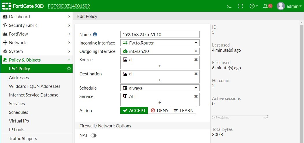

Lúc này thì VL10 đã có thể gửi được dữ liệu tới mạng LAN 192.168.2.0/24 và ngược lại.
|
Router# ping 172.16.10.2 source 192.168.2.1 |
Bước 6. Định nghĩa Address Object tương ứng với VLAN 10 và mạng LAN 192.168.2.0/24.
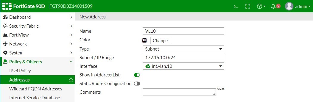


Bước 7. Hiệu chỉnh IPv4 Policy cho phép VLAN 10 có thể giao tiếp được với mạng LAN 192.168.2.0/24 tương ứng với Source và Destination cụ thể.
4. Cấu hình định tuyến động RIP trên Firewall FortiGate.
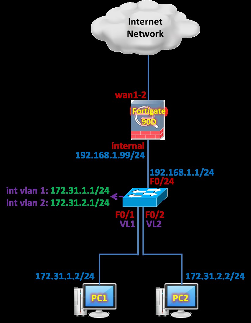
Tổng quan các bước thực hiện:
Bước 1. Cấu hình cơ bản và RIP trên Cisco Switch.
Bước 2. Cấu hình RIP trên Firewall Fortigate.
Chi tiết các bước thực hiện:
Bước 1. Cấu hình cơ bản và RIP trên Cisco Switch.
|
hostname Sw1 default interface f1/0/1 interface f1/0/1 switchport trunk encapsulation dot1q switchport mode trunk spanning-tree portfast trunk exit
vlan 2 exit default interface f1/0/2 interface f1/0/2 switchport trunk encapsulation dot1q switchport mode trunk switchport trunk native vlan 2 spanning-tree portfast trunk exit
interface vlan 1 ip address 172.31.1.1 255.255.255.0 no shutdown exit interface vlan 2 ip address 172.31.2.1 255.255.255.0 no shutdown exit
ip dhcp excluded-address 172.31.1.1 ip dhcp pool LAN1 network 172.31.1.0 255.255.255.0 default-router 172.31.1.1 dns-server 8.8.4.4 exit ip dhcp excluded-address 172.31.2.1 ip dhcp pool LAN2 network 172.31.2.0 255.255.255.0 default-router 172.31.2.1 dns-server 8.8.4.4 exit
default interface f1/0/24 interface f1/0/24 no switchport ip address 192.168.1.1 255.255.255.0 exit ip routing no ip route 0.0.0.0 0.0.0.0 192.168.1.99 router rip version 2 network 192.168.1.0 network 172.31.0.0 no auto-summary exit
line vty 0 4 privilege level 15 no login transport input telnet exit no ip domain-lookup |
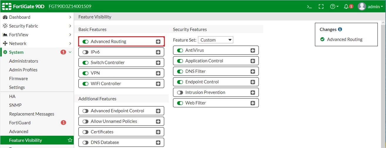
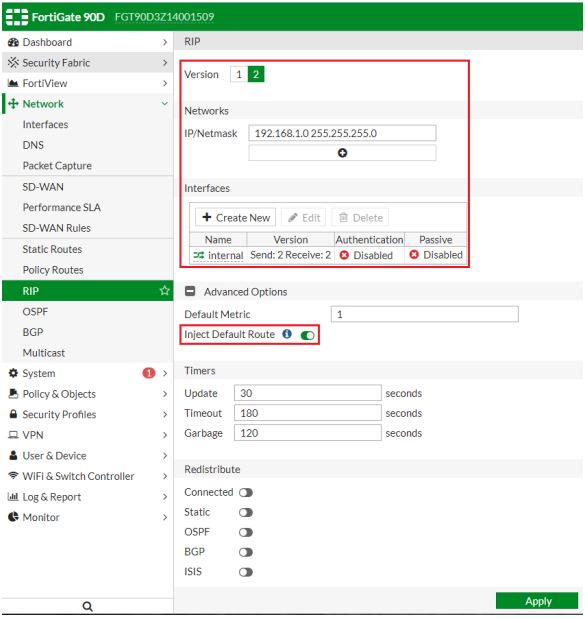
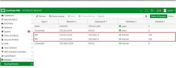
Bước 2. Cấu hình RIP trên Firewall Fortigate.

5. Cấu hình định tuyến động OSPF trên Firewall FortiGate.

Tổng quan các bước thực hiện:
Bước 1. Cấu hình cơ bản và RIP trên Cisco Switch.
Bước 2. Cấu hình OSPF trên Firewall Fortigate.
Chi tiết các bước thực hiện:
Bước 1. Cấu hình cơ bản và RIP trên Cisco Switch.
|
hostname Sw1
default interface f1/0/1 interface f1/0/1 switchport trunk encapsulation dot1q switchport mode trunk spanning-tree portfast trunk exit
vlan 2 exit default interface f1/0/2 interface f1/0/2 switchport trunk encapsulation dot1q switchport mode trunk switchport trunk native vlan 2 spanning-tree portfast trunk exit
interface vlan 1 ip address 172.31.1.1 255.255.255.0 no shutdown exit interface vlan 2 ip address 172.31.2.1 255.255.255.0 no shutdown exit
ip dhcp excluded-address 172.31.1.1 ip dhcp pool LAN1 network 172.31.1.0 255.255.255.0 default-router 172.31.1.1 dns-server 8.8.4.4 exit ip dhcp excluded-address 172.31.2.1 ip dhcp pool LAN2 network 172.31.2.0 255.255.255.0 default-router 172.31.2.1 dns-server 8.8.4.4 exit
default interface f1/0/24 interface f1/0/24 no switchport ip address 192.168.1.1 255.255.255.0 exit ip routing no ip route 0.0.0.0 0.0.0.0 192.168.1.99
router ospf 1 router-id 0.0.0.1 network 192.168.1.0 0.0.0.255 area 0 network 172.31.1.0 0.0.0.255 area 0 network 172.31.2.0 0.0.0.255 area 0 exit
line vty 0 4 privilege level 15 no login transport input telnet exit no ip domain-lookup |
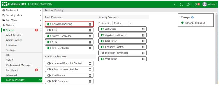
Bước 2. Cấu hình OSPF trên Firewall Fortigate.


6. Cấu hình định tuyến động BGP trên Firewall FortiGate.
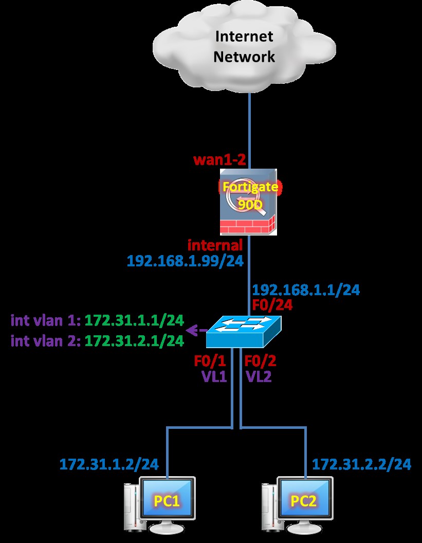
Bước 1. Cấu hình cơ bản và BGP trên Cisco Switch.
| hostname Sw1
default interface f1/0/1 interface f1/0/1 switchport trunk encapsulation dot1q switchport mode trunk spanning-tree portfast trunk exit
vlan 2 exit default interface f1/0/2 interface f1/0/2 switchport trunk encapsulation dot1q switchport mode trunk switchport trunk native vlan 2 spanning-tree portfast trunk exit
interface vlan 1 ip address 172.31.1.1 255.255.255.0 no shutdown exit interface vlan 2 ip address 172.31.2.1 255.255.255.0 no shutdown exit
ip dhcp excluded-address 172.31.1.1 ip dhcp pool LAN1 network 172.31.1.0 255.255.255.0 default-router 172.31.1.1 dns-server 8.8.4.4 exit ip dhcp excluded-address 172.31.2.1 ip dhcp pool LAN2 network 172.31.2.0 255.255.255.0 default-router 172.31.2.1 dns-server 8.8.4.4 exit
default interface f1/0/24 interface f1/0/24 no switchport ip address 192.168.1.1 255.255.255.0 exit ip routing no ip route 0.0.0.0 0.0.0.0 192.168.1.99
router bgp 1 bgp router-id 192.168.1.1 neighbor 192.168.1.99 remote-as 99 network 172.31.1.0 mask 255.255.255.0 network 172.31.2.0 mask 255.255.255.0 exit
line vty 0 4 privilege level 15 no login transport input telnet exit no ip domain-lookup |
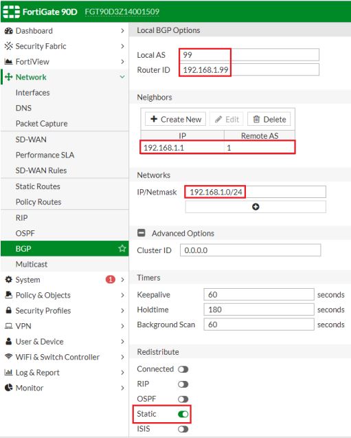
Bước 2. Cấu hình OSPF trên Firewall Fortigate.


7. Cấu hình kỹ thuật chia tải lưu lượng SD-WAN trên Firewall Fortigate.
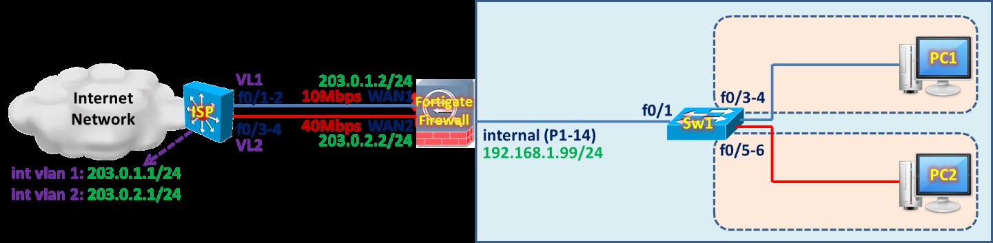
Các bước cấu hình kỹ thuật chia tải lưu lượng SD-WAN trên Firewall Fortigate.
- Bước 1. Gỡ bỏ cấu hình DefaultRoute và Default Internet Access Policy.
- Bước 2. Thiết lập SDWAN Interface.
- Bước 3. Cấu hình SDWAN Load Balancing.
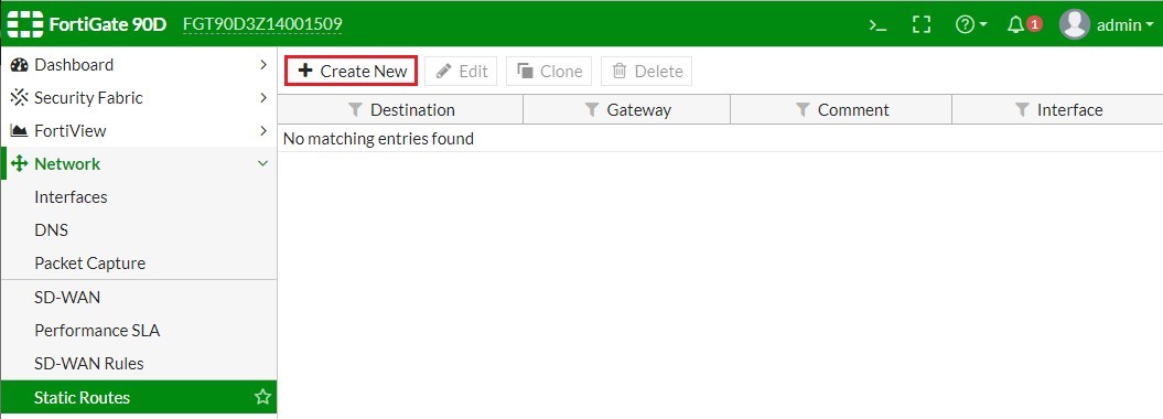
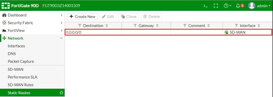
- Bước 4. Thiết lập Static Route tương ứng với the SDWAN Interface.
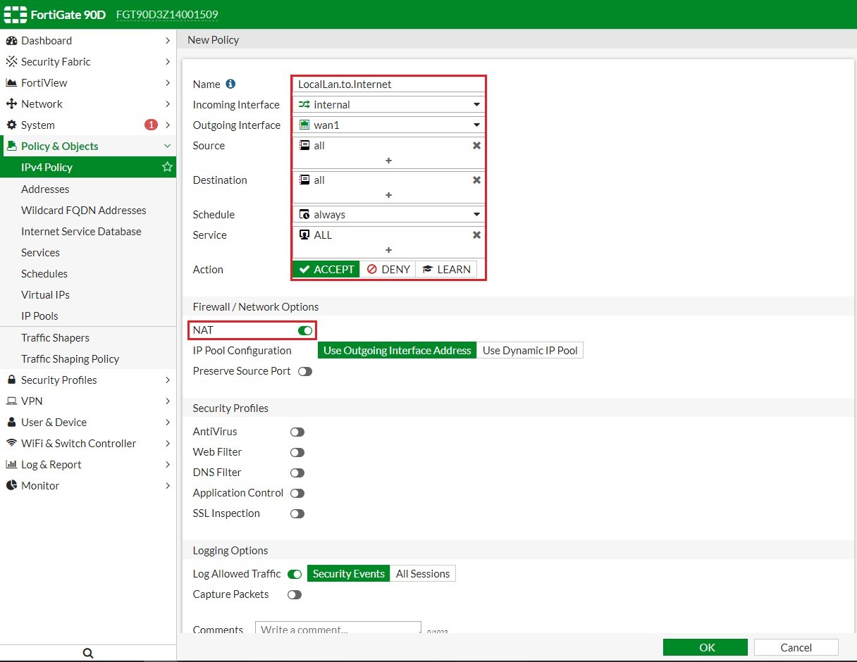
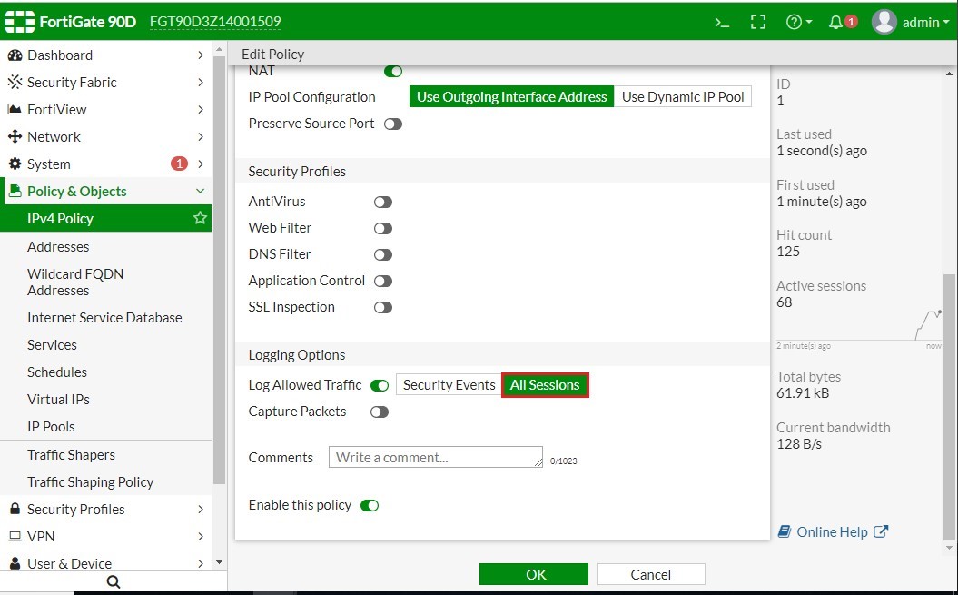
- Bước 5. Cấu hình Security Policy cho phép lưu lượng bên trong hệ thống mạng nội bộ truy cập Internet thông qua SDWAN Interface.
- Bước 6. Cấu hình Link Health Monitoring để kiểm tra Health & Status của các Links liên quan đến SDWAN Link.
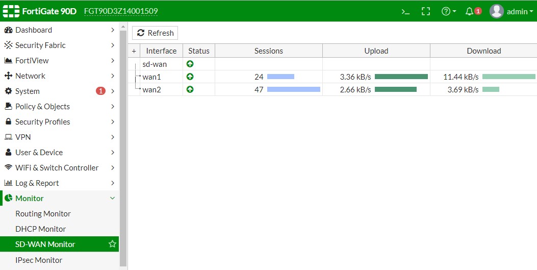
- Bước 7. Kiểm tra tỉ lệ cân bằng tải trên SDWAN Interface.
Bước 1. Gỡ bỏ cấu hình DefaultRoute và Default Internet Access Policy.
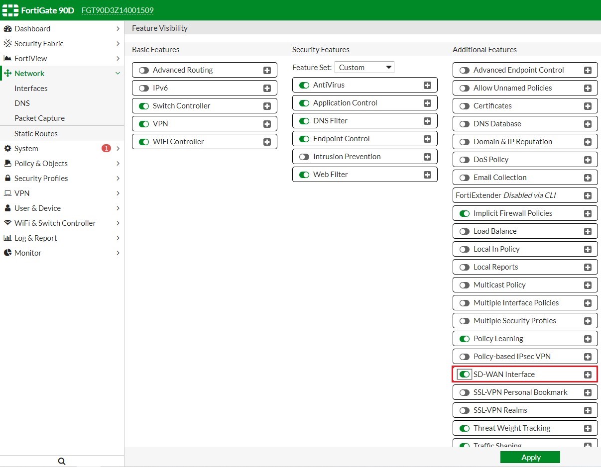
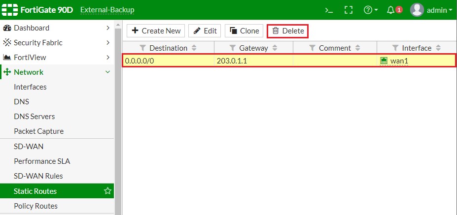
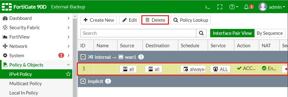
Bước 2. Thiết lập SD-WAN Interface.


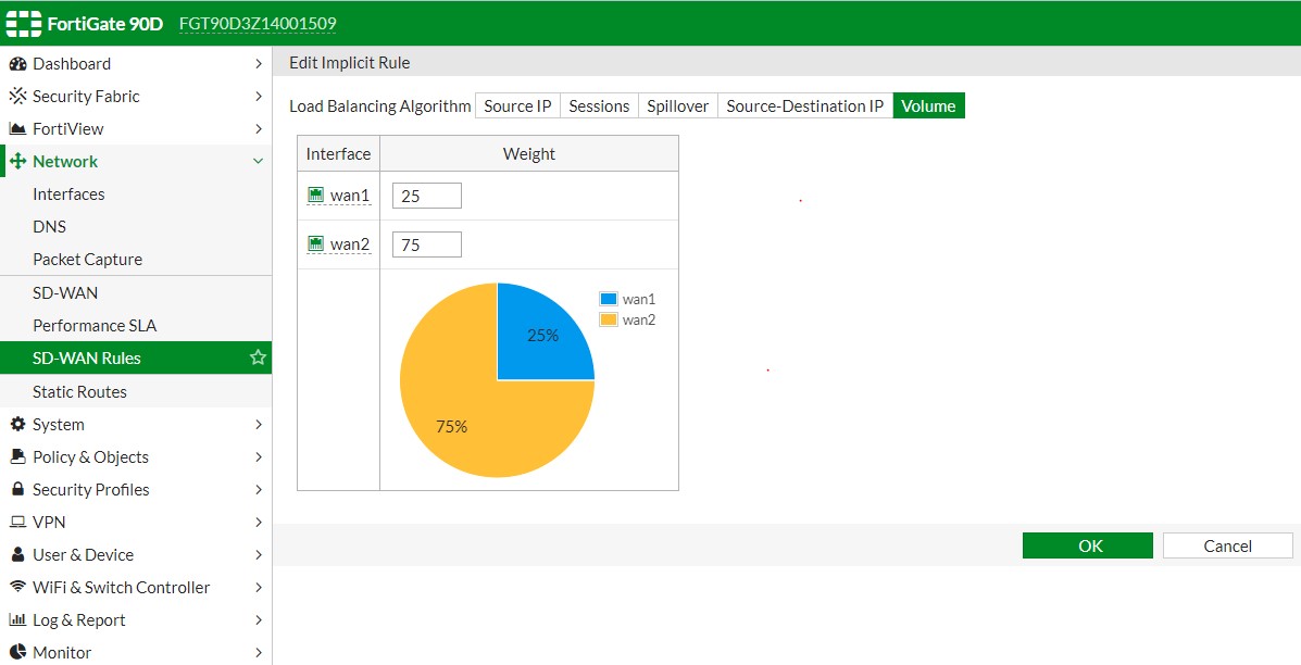
Bước 3. Cấu hình SD-WAN Load Balancing.
The ISP connected to WAN1 is a 40Mb link, and the ISP connected to WAN2 is a 10Mb link, so we balance the weight 75% to 25% in favor of WAN1.

Bước 4. Thiết lập Static Route tương ứng với the SD-WAN Interface.

Bước 5. Cấu hình Security Policy cho phép lưu lượng bên trong hệ thống mạng nội bộ truy cập Internet thông qua SD-WAN Interface.


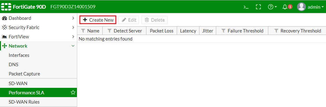
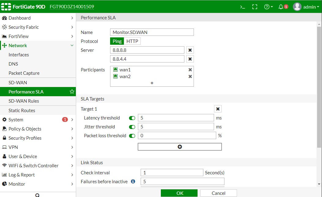
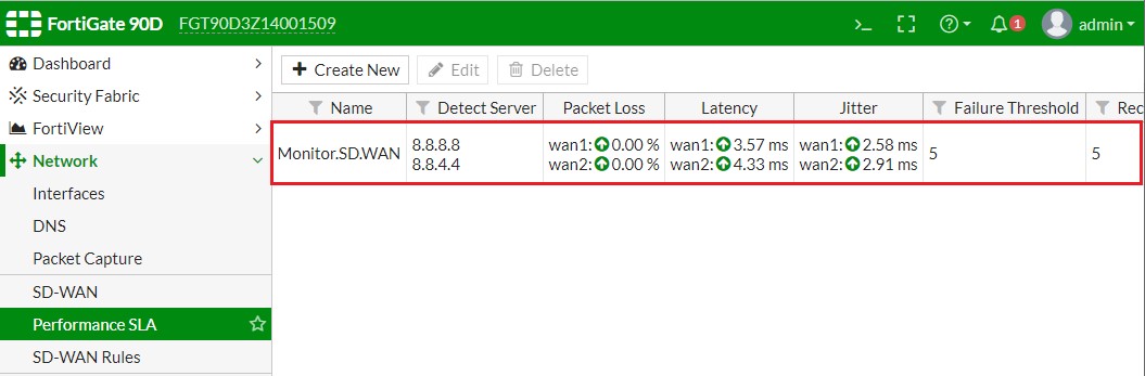
Bước 6. Cấu hình Link Health Monitoring để kiểm tra Health & Status của các Links liên quan đến SD- WAN Link.
Bước 7. Kiểm tra tỉ lệ cân bằng tải trên SD-WAN Interface.

Kết thúc Phần I


